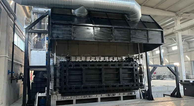
Billet Casting manufactures Regenerative Melting Furnace in different capacities upon request. Capacity is calculated and projected according to the casting capacity needs of your foundry. This furnace, in which a Regenerative Combustion System is used, provides fuel savings of up to 40% compared to other industrial furnaces.
SPECIFICATION FOR MELTING FURNACES
FUEL Natural Gas, 300 Nm3/h
Pressure at entry, 300 mbar
Calorific value assumed 3.000 kcal/NM3
ELECTRICITY 380V, 3 phase, 50 Hz
220V, single phase, 50Hz
24V DC for controls
COMPRESSED AIR 8 Bar
FURNACE DATA
FURNACE TYPE Tilting Furnace with Regenerative Burner
LIQUID METAL MAX CAPACITY 35 tons
MAX METAL TEMPERATURE 780 oC
AVERAGE BATH DEPTH 650 mm
DOOR SILL LINE OVER BATH LEVEL 100 mm
NUMBER OF DOOR 1
DOOR OPERATION Hydraulic
DOOR SIZE 1500mm x 4750mm
COMBUSTION SYSTEM
TOTAL BURNER CAPACITY 5.000.000 kcal x 2 regenerative burner
Melting Capacity 2 times charge per day with %50 scrap
3 times charge per day with %5 scrap
BURNER IGNITION By spark ignited pilot burners
FLAME SUPERVISION Automatic supervision by ignition rod and flame relay
TEMPERATURE CONTROL Automatic over bath and roof thermocouples
AUTOMATION AND ELECTRICAL EQUIPMENTS
Brand: ABB ( PLC,AC driver,circuit breaker,contactor,All equipment brand will be ABB
Also Electrical Panel have air condition system
REGENERETIVE BURNER DESCRIPTION
The furnace will be heated up by means of one pair regenerative hot air burners which are located in a side wall angled to ensure good heat transfer to the charge and to provide effective circulation of hot combustion gases within the furnace.
A regenerative burner is a combustion heating system allowing extremely high-efficient recovery of exhaust heat in the industrial furnace.
Regenerative burner system ignites a pair of burners integrated with the heat reservoirs alternately at intervals of several tens of seconds. While one burner is burning, the exhaust gas passes through and heats the other burner’s heat reservoir to recover the energy of the exhaust gas. Then, when the other burner burns, the air for combustion in turn passes through the preheated heat reservoir to recover the exhaust gas energy which had conventionally been wasted, to provide high efficient combustion.
Each burner will incorporate individual air/fuel ratio regulation which will be controlled by valves in the fuel and air lines,as will the burner firing rate.
The burners will be ignited by spark ignited pilot burners. An ultra violet scanner, to control the burner flame, will be mounted on the burners with a programmed relay unit located in a control panel.
Combustion air for the main burners and pilot burners will be provided by seperate high pressure blowers.
Exhaust gases will be sucked by an exhaust blower.
Safety controls will be incorporated in the combustion system including fuel and air pressure switches, solenoid operated fuel shut-off valves, purge sequencing, governors and fuel isolating valves.
Control Panel
All the necessary equipment for controlling and operating the furnace is contained in a dust tigh control panel. The control panel is to be positioned in a convenient location adjacent to the furnace.
During furnace operation, the various furnace conditions and functions as well as alarms will be indicated on an annunciator panel built into the front of the control panel.
The built-in automatic ignition programmer ensures that only the correct ignition sequence is followed. The furnace temperature control is automatic. In the event of furnace roof over temperature, the safety controller will shut the burners down and an alarm will sound.
The control panel will be equipped with indicating readouts and control instrumentation for the necessary operation ;
• bath temperature
• roof temperature
• furnace pressure
• flame failure programming units
All mains voltage functions such as transformers and motor starters would be housed in a separate compartment in the same panel. The panel would be fully internally wired in trunking with terminal blocks and the front face would incorparate all lights,buttons and labels as necessary. The panel would be shop tested before delivery.
Site Wiring
The Customer will supply all mains power and control wiring, cable trays, junction boxes,glands,etc., between the control panels on or near the furnace and all ORAY supplied items on or adjacent to the furnace.
SCOPE OF SUPPLY
• Combustion system comprising burners, regenerative beds, heat storage media, combustion air fan, exhaust fan, pilot burners fan, change over valves, selonoid valves, control valves, flexes, trimming valves, isolating cocks, pressure switches, flame relays and ignition system.
• Geared motor unit, ceramic seals, limit switches, clamping cylinders, bearings, chains and chainwheels for main door.
• Pneumatic actuator bearings and pressure transducer for damper.
• Pneumatic control, regulation and conditioning units for door and exhaust damper.
• Pivot type pouring spout and knuckle assembly.
• Launder metal level float control system.
• Thermocouples for molten metal and roof temperature monitoring.
• Composite suite of panels housing the electrical control safety system.
• Refractory materials.
• Steel fabrication and machined steel components including furnace casing and structural steel, packs and shims, motor brackets, door, door structure, brackets, door frame and balance weight, exhaust duct, fume hood