HOMOGENIZATION FURNACE TECHNICAL
SPECIFICATIONS Fuel:
Natural Gas, 300 Nm³/h
Inlet Pressure: 300 mbar
Calorific Value: 11,000 kcal/Nm³ (LPG equivalent)
Electricity: 380V, 3-phase, 50 Hz
Compressed Air: 7 bar
Furnace Data
Internal Length: 6800 mm
Maximum Load Length: 6500 mm
Number of Circulation Fans: 3 x 30,000 m³/h @ 125 mmWC
Burner Control Zones: 3
Burner Capacity per Zone: 500,000 kcal/h x 3
Operating Temperature Range: 550–650 °C
Descriptions
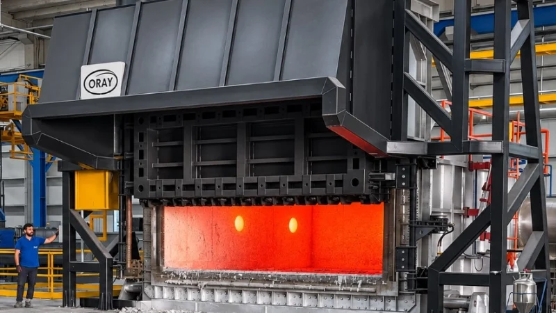
Furnace Body:
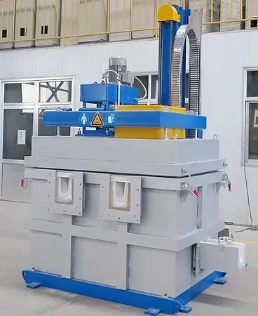
The furnace body shall be constructed from 5 mm thick mild steel plates, fully welded and reinforced with rolled steel profiles, ensuring a robust and rigid structure.
The furnace shall be heavily insulated to minimize heat loss, reduce thermal mass for optimal efficiency, and accommodate thermal cycling requirements.
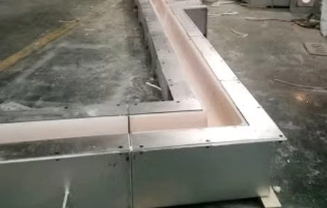
The side walls shall be lined with low-resin mineral wool and ceramic fiber blankets, totaling 300 mm in thickness, installed with overlapping joints and no gaps. Following the installation of the insulation, the furnace roof and walls will be clad with pressed stainless steel panels, secured in place by channels attached to the outer casing using hook bolts. This system ensures minimal metal-to-metal contact and maintains a very low casing temperature.
Door Operating Mechanism
The door will be constructed from mild steel plates, reinforced internally with steel profiles, insulated, and clad with pressed panels similar to those used for the furnace casing. Vertical movement of the door will be powered by an electric geared motor equipped with an integrated brake.
The door will be suspended by two chains, connected to a counterweight via sprockets mounted on shafts that are supported by bearing units on the overhead structural steel frame.
When the door is in the “down” position, a clamping mechanism shifts it horizontally to create a positive seal, preventing cold air from entering the furnace chamber. A ceramic fiber gasket will be installed around the perimeter of the door.
Recirculation System:
Recirculation fans will be mounted on the side wall of the furnace, and air will circulate through stainless steel ducts that form a false ceiling within the working chamber.
Due to the aerodynamic design of the furnace, the air is distributed uniformly and passes over the load at high velocity, facilitating heating via forced convection.
The speed of the recirculation fans will be regulated by AC motor drives (frequency controllers) based on the furnace temperature.
The fan rotors and shafts will be fabricated from 310-grade stainless steel. TECHNICAL SPECIFICATIONS FOR THE
COOLING CHAMBER
NOMINAL CAPACITY: 17 Tons
INTERNAL LENGTH: 7800 mm
DOOR OPENING WIDTH: 2200 mm
TOTAL WIDTH: 4500 mm
TOTAL LENGTH: 7000 mm
COOLING FANS: (3 x 60,000 m³/h)
MOTOR SIZE (Option 1): 30 kW
COOLING DURATION: 3.5 hours
INITIAL COOLING RATE: 300 °C/h
ELECTRICAL SUPPLY: 380 V, 3-phase, 50 Hz
Cooling Chamber Structure
The cooling chamber shall be constructed from 4 mm thick steel plate, reinforced with steel profiles to form a rigid, floor-mounted unit.
The load shall be supported on heavy-duty rolled steel beams, positioned longitudinally atop vertically mounted tubular supports—a configuration similar to that of a furnace hearth.
Access shall be provided via a shutter-style door.
Cooling System
Cooling fans shall be mounted on pedestals along the side walls of the chamber, designed to draw air horizontally across the load at high velocity to ensure rapid and uniform cooling of the billets.
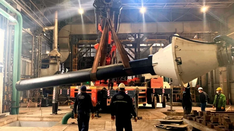
The fan assemblies shall include V-belt drives, fabricated support stands, safety guards, motors, fan housings, bearings, heavy-duty shafts, and backward-inclined impellers. Air will be drawn into the fans from the plenum section of the chamber through dedicated fan inlet cones and via duct sections equipped with strategically positioned, adjustable louvers, ensuring an even airflow across the entire load.
Control Panel
The control panel will consist of a floor-mounted unit housing motor contactors, illuminated push-buttons, and a terminal rail for field wiring.
System Design Parameters
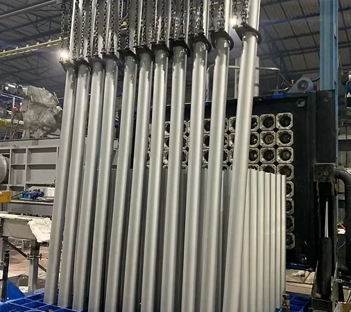
The cooling system is designed to cool a load of billets—each 203 mm in diameter, with a total mass of 30,000 kg—from 580 °C to 100 °C within 3.5 hours.
The initial cooling rate, which is critical for achieving optimal metallurgical properties, will be a minimum of 300 °C/hour.
The large volume of circulating air will ensure rapid and uniform cooling.
SCOPE OF SUPPLY
- Electric motor-driven fans
- Steel-constructed frame and load supports
- Shutter-style door
LOADING CAR FOR HOMOGENIZATION FURNACE
SPECIFICATIONS
MAXIMUM LOAD: 17 tons
MAXIMUM LOAD LENGTH: 7400 mm
MAXIMUM LOAD WIDTH: 1800 mm
FORK EXTENSION: 7600 mm
LOAD-CARRYING PLATFORM WIDTH: 1400 mm
LOAD-CARRYING LIFT: 70 mm
NUMBER OF TRACK WHEELS: 6
DISTANCE BETWEEN TRACK WHEEL CENTERS: 2500 mm
TRACK WHEEL DIAMETER: 500 mm
TOTAL LENGTH: 9000 mm
PROPULSION: Hydraulic
TRAVEL SPEED: 10 m/min
LOAD LIFTING: Hydraulic
LOAD-LIFTING DRIVE: Hydraulic
LOAD-LIFTING SPEED: 10 seconds
LOAD-CARRYING SPEED: 6 m/min
DESCRIPTION
General
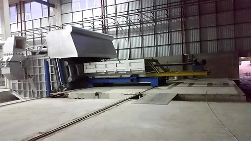
The charging machine shall be constructed from properly supported and reinforced rolled steel profiles to ensure a rigid structure. An operator platform, equipped with a control console and a heat-resistant screen, shall be integrated into the rear of the unit.
Movement shall be achieved via a system supported by the base frame, utilizing hydraulically operated gearboxes, driven bogie-type wheels, and shaft and bearing assemblies. The load carrier shall be supported by wheel assemblies and driven by a rack-and-pinion mechanism, which operates in conjunction with a helical gearbox and an associated hydraulic motor.
Movement Functions
To facilitate the transport of loads to and from the furnace, cooler, and loading stations, the following movements can be performed:
- Forward and backward movement of the entire machine along rails throughout the workshop.
- Advancement of the load carrier toward the furnace, cooler, or loading station.
- Raising or lowering of the carrier platform to pick up or deposit a load.
Main Frame and Drive Mechanism
The main frame shall be constructed from rolled steel profiles, suitably reinforced to ensure a robust and rigid structure.
Dual rail tracks shall be installed on top of the main frame to support and guide the load carrier assembly.
The travel wheels shall be arranged on axles and mounted to the main frame via bearing units. The wheels on one side of the machine shall be interconnected by a line shaft to ensure synchronized movement during operation. This drive system shall consist of a gearbox and a hydraulic motor.
Load Carrying Unit and Lifting Mechanism
The lower section shall incorporate wheel assemblies that travel along rails located on the machine and at the furnace/loading station sites. The wheels shall feature integrated ball bearings and rotate on axles housed within the load-carrying frame. The upper sections, or the load platform, shall be connected to the load-carrying frame via linkages that allow the platform to be raised or lowered by means of hydraulic cylinders.
The load-carrying unit shall be driven by a gear mechanism extending along the entire length of the undercarriage. This gear mechanism shall engage with a sprocket located at one end of the main frame.
The chain drive shall be powered by a hydraulic motor, connected through a gear unit equipped with bearings and a drive shaft.
Hydraulic Power Unit
The hydraulic power unit, which supplies the drives, shall be positioned at the rear of the machine and connected to the cylinders and drive motors via an appropriate arrangement of rigid piping and flexible hoses.
Electrical Controls
The electrical control equipment shall be housed in a control panel located at the rear of the machine.
The control equipment shall include an isolator, a motor starter for the hydraulic pump, relays, indicator lights, etc.
SCOPE OF SUPPLY
- Fabricated steel frame, wheel housing, platforms, heat shield, carrying forks, positioning bolt strikers, and brackets.
- Machined wheels, shafts, and levers.
- Gear units, couplings, bearings, chains, and sprockets.
- Hydraulic power unit.
- Electrical control panel.
- Mechanical assembly of the machine. • Steel fabrication and machined steel components, including the furnace body and structural steel, packs and shims, motor brackets, furnace load supports and rails, the door, door structure, brackets, door frame and counterweight, exhaust duct, and stainless steel cladding.